Author
Logan Johnson
Evidence
Published specs, catalog receipts, owner-reported failure patterns
Policy
No sponsored placementsAt a Glance
Best For
Overview
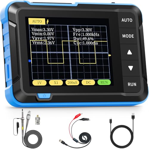
The FNIRSI P02 is a USB oscilloscope probe set that costs $49 and answers a question that comes up constantly on electronics hobbyist forums: 'Do I need a real oscilloscope, or will a USB scope do it?' For a soldering bench focused on firmware debugging, serial communication verification, and general analog signal checking — the P02 does it, at a price that removes the barrier to having oscilloscope capability at all.
A USB scope isn't a replacement for a dedicated bench oscilloscope. It has narrower bandwidth, lower sample depth, and fewer trigger options than even a budget standalone scope like the Hantek DSO5102P. What it has is zero footprint, zero warm-up, and zero friction: plug it in, open the software, probe the signal. For the debugging sessions where you're spending 30 minutes chasing a firmware timing issue or verifying an I2C clock speed, the P02 is faster to set up than a dedicated scope and fast enough to solve the problem.
At 50MHz bandwidth with two channels, the P02 covers the frequency range of most embedded signal debugging: UART at 115200 baud (well below 1MHz), I2C at 100kHz and 400kHz, SPI at up to a few MHz, PWM signals, audio-range analog, and power supply ripple. It doesn't cover RF work, high-speed digital above 50MHz, or precision analog characterization. It handles what a repair bench actually needs most of the time.
Pros & Cons
Pros
- No PC software needed — runs via USB-C as a USB scope directly
- 50MHz bandwidth sufficient for most digital signal debugging (I2C, SPI, UART)
- Compact enough to keep on the bench without dedicated scope space
- Includes 2 probes for comparing clock vs data simultaneously
- Works on Windows, Mac, and Linux without drivers
- Adds real capability at an impulse-buy price
Cons
- Not a replacement for a real oscilloscope — sample depth and trigger options limited
- USB bandwidth means slower waveform update rate than dedicated hardware
- No external trigger input
- Software UI is functional but not polished
FNIRSI P02 USB Oscilloscope Probe Set
Prices may change · Free shipping with Prime
50MHz Bandwidth — What It Covers and Where It Runs Out
Bandwidth in an oscilloscope is the upper frequency limit at which the scope accurately represents the signal. Signals above the bandwidth limit are attenuated — the scope shows them at lower amplitude than reality, and at very high frequencies, doesn't show them at all. The -3dB point at 50MHz means a 50MHz sine wave is shown at about 70% of its true amplitude; anything significantly above 50MHz is unreliable.
For the most common embedded debugging scenarios, 50MHz is adequate. UART communication at even the fastest standard rates (1Mbaud = 1MHz fundamental frequency, far below 50MHz). I2C at 100kHz, 400kHz, or even the 3.4MHz fast-plus mode is well within bandwidth. SPI at up to 10MHz common clock rates is covered comfortably. PWM signals from 1Hz to 2MHz are measurable accurately. Audio-frequency signals (20Hz to 20kHz) are trivially within bandwidth.
Where 50MHz hits its limits: USB Full Speed (12Mbps has frequency content to ~60MHz), USB High Speed (480Mbps — far beyond), SPI at 25MHz+ clock rates (some fast Flash chips, display controllers), and any RF or high-speed serial work. For those applications, you need a scope with 100–200MHz bandwidth minimum.
Practically, a soldering bench's primary oscilloscope need is serial communication debugging, power supply ripple analysis, and basic analog signal verification. The P02 handles all three. The scenarios where it falls short are scenarios that would justify a standalone scope regardless — if you're regularly working at 100MHz+, buy a proper scope.
Two Channels — How to Use Them Together for Common Debugging Scenarios
The P02's two channels aren't just two inputs — they're the capability that makes timing analysis possible. Single-channel scopes show one signal; two channels let you compare signals simultaneously, measure phase relationships, and analyze multi-signal protocols.
The most common two-channel debugging scenario: I2C protocol analysis. I2C uses two lines — SDA (data) and SCL (clock). Connect channel 1 to SDA, channel 2 to SCL, trigger on a data edge, and you can see exactly where data transitions fall relative to clock edges. This is the fastest way to diagnose I2C address conflicts, ACK failures, and bus contention without a dedicated logic analyzer.
SPI debugging uses the same approach: connect one channel to MOSI and one to SCK, trigger on the chip select line if your scope supports it, and you see data pulses aligned with clock edges. This is invaluable for verifying SPI timing when a peripheral isn't responding as expected.
Power integrity analysis is another two-channel use: connect one channel to a supply rail, one channel to a signal that's behaving incorrectly, and look for correlation between supply noise and signal glitches. Many 'software bugs' in embedded systems are actually power supply coupling issues visible on a two-channel scope and invisible when debugging code.
For bench work where one common failure mode is 'this sensor / display / peripheral is doing something weird,' the two-channel P02 gives you the diagnostic capability to correlate the 'weird' signal against the reference signal and understand what's actually happening.
Software and PC Integration — Setup and Practical Limitations
The FNIRSI P02 runs as a USB HID device — no custom drivers required on Windows, Mac, or Linux. It powers from the USB port and presents itself as a USB human interface device. The companion software (available from FNIRSI's site) provides the oscilloscope UI: waveform display, trigger configuration, time base, channel scaling, and basic measurements (frequency, period, duty cycle, amplitude).
Setup is genuinely straightforward: install software, plug in the P02, launch the software, start probing. Unlike early-generation USB scopes that required driver installation, firmware flashing, or finicky USB compatibility, the P02 works without friction on modern systems.
The software is functional but not polished. The UI is visually consistent with a budget embedded scope interface — it works, all the controls are where you expect them, but it won't win design awards. There are no advanced trigger modes (runt pulse, timeout, serial protocol decode) that higher-end scopes provide. For standard edge triggering and threshold triggering, it's adequate. For complex trigger scenarios, you've hit the ceiling.
The USB bandwidth limitation creates one real constraint: waveform update rate. A standalone scope refreshes its display thousands of times per second. The P02, sending waveform data over USB, updates at roughly 30–60 frames per second in real-world use. This is fast enough for most measurement work but means intermittent glitches on slowly-repeating events may not display on every trigger occurrence. For capturing rare or intermittent events reliably, a standalone scope with onboard memory is the right tool.
The Right Use Case — Where the P02 Belongs on Your Bench
The P02 is the right tool for a specific bench profile: primarily soldering and repair work, with oscilloscope needs that arise regularly but not as the primary diagnostic tool, and where desk space and budget don't support a full standalone scope.
For firmware debugging on Arduino, ESP32, STM32 — verifying UART output, checking I2C timing, confirming SPI transactions — the P02 is faster to deploy than a logic analyzer and gives you analog signal information that a logic analyzer doesn't. You can see the actual voltage level of an I2C SDA line during a communication failure, not just the logical state.
For power supply design and repair, the P02 verifies ripple on output rails, checks switching waveforms on SMPS designs at reasonable clock rates, and confirms regulation behavior under load. This is exactly the kind of quick verification work that takes 2 minutes with a probe versus 20 minutes of careful DC measurement trying to infer dynamic behavior from static readings.
For audio work — checking amplifier output, verifying oscillator circuits, measuring THD by eye on a sine wave — the P02's bandwidth is far more than sufficient and its two channels let you compare input and output simultaneously.
Where you'll outgrow it: any RF work, high-speed digital work above 20MHz clock rates, applications requiring hardware triggering on protocol conditions, and production test setups where consistency and precision matter more than cost. At that point, even a budget standalone scope (DSO5102P at $120) is a better investment.
Pairing the P02 With Your Soldering Station — The Complete Signal Analysis Setup
The FNIRSI P02 doesn't replace a logic analyzer for protocol work — it complements one. For a bench doing both hardware repair and firmware development, the ideal signal analysis toolkit looks like: P02 USB scope for analog and timing, plus a cheap 24MHz Saleae clone for protocol decode.
Here's the practical division of labor. The P02 handles: 'Is this power rail clean?', 'What does this PWM signal look like in the time domain?', 'Why is this UART byte getting corrupted at this baud rate?', 'Is there noise on this analog sensor output?'. The logic analyzer handles: 'Can you decode this I2C transaction and tell me what's being sent?', 'Why is this SPI device not responding — decode the complete transaction', 'Log 10,000 UART bytes automatically.'
The two tools together cost $49 (P02) + $15 (clone logic analyzer) = $64 and cover a large fraction of the embedded debugging scenarios a repair tech or firmware developer encounters. Neither tool alone covers the full space; together they do.
For the soldering bench where the primary activity is board repair (no firmware development), the P02 standalone is sufficient for the occasional 'does this signal look right?' check without the overhead of a standalone scope. Buy the logic analyzer when you start doing protocol-level debugging regularly.
Our Verdict
The FNIRSI P02 is the best 'good enough' USB scope for a soldering bench. If you debug Arduino/ESP firmware, verify PWM signals, or check I2C traffic, it saves hours of print-statement debugging. Not a standalone scope replacement — a perfect $50 complement.
FNIRSI P02 USB Oscilloscope Probe Set
$49
Prices may change · Free shipping with Prime
| Full Specifications | |
|---|---|
| Station Type | USB Oscilloscope Probe |
| Wattage | 0W |
| Temp Range | N/A |
| Temp Stability | 0±°C |
| Tip System | Probe Clips |
| Digital Display | No |
| Temp Lock | No |
| Sleep Mode | No |
| Hot-Air Channel | No |
| Channels | 2 |
| Unit Weight | 0.3lbs |
Frequently Asked Questions
Does the FNIRSI P02 work on Linux and Mac, or only Windows?
Is 50MHz bandwidth enough for debugging I2C and SPI communication?
How does the P02 compare to a budget standalone scope like the Hantek DSO5102P?
Can I use the FNIRSI P02 as a basic data logger for slow signals?
Compare With Similar Bench Tools
Head-to-Head Comparisons
FNIRSI P02 USB Oscilloscope Probe Set
$49
Prices may change · Free shipping with Prime